Design and Functionality of Indoor & Greenhouse Irrigation Systems

In this article we will break down the design and functionality of indoor and greenhouse irrigation systems. This basic overview will provide an understanding as to whether your components are properly sized, and maximizing the full functionality of a fertigation/irrigation system, to ensure you install things correctly the first time.
When designing an irrigation system we like to work in two directions. (1) From the water room going out, and (2) from the zones containing plants backwards. What this means is that information from the zones needs to pair with the engineering in the water room and the lines in between.
There are many questions that need to be asked pertaining to costs, functionality, water consumption, zone sizing, etc. to assist in understanding this process. Let’s pose and answer some of the most common questions we ask when building a new system.
QUESTION #1 – HOW MANY ZONES DO I NEED?
A zone is the area you plan on irrigating at any given time. If you are feeding a single bench one at a time, then a single bench is a zone. If you are feeding an entire room containing 5 benches of plants, then your zone is that room of 5 benches. You can also think of a zone in terms of solenoid valves since generally these valves control watering.
Irrigation and fertigation systems are designed around flow rates. In order to come up with the right flow rates, first we need to divide the facility into zones. Once you have the zones and flow rates, then you can decide on PVC pipe sizes, commercial water irrigation pump sizes, water storage tank sizes, etc.
Zones should be divided to the largest quantity one can reasonably deal with at once, taking into account the total size of the cultivation facility. That means environmental conditions, planting and harvesting, labor, and workability are all in a range that makes sense. Normal zones are a single bench for a small boutique farm, a room or bay for a medium sized indoor grow or greenhouse, or a full greenhouse or field for multi-acre properties.
Here is an example of a facility ZONE MAP containing 14 zones:
Veg Room
-
Irrigate the entire room at once
-
Zone 1 – 5000 Plants
Flower Room
-
Irrigate the entire room at once
-
Zone 2 – 2000 Plants
Flower Room
-
Irrigate the entire room at once
-
Zone 3 – 300 Plants
Flower Room
-
Irrigate the entire room at once
-
Zone 4 – 500 Plants
Flower Room
-
Irrigate the entire room at once
-
Zone 5 – 500 Plants
Flower Room
-
Irrigate the entire room at once
-
Zone 6 – 500 Plants
Flower Room
-
Irrigate the entire room at once
-
Zone 7 – 200 Plants
Flower Room
-
Irrigate the entire room at once
-
Zone 8 – 500 Plants
Flower Room
-
Irrigate the entire room at once
-
Zone 9 – 500 Plants
R & D Room
-
Irrigate each bench individually
-
Zone 10 – 100 Plants
-
Zone 11 – 100 Plants
-
Zone 12 – 100 Plants
-
Zone 13 – 100 Plants
-
Zone 14 – 100 Plants
QUESTION #2 – WHAT ARE MY REQUIRED FLOW RATES?
Flow rates are determined by getting plant counts per zone and multiplying that number by the number of emitters and their respective flow rates.
For example, if a zone has 100 plants and each plant has 2 emitters that are 0.3 Gallons Per Hour (GPH) then the equation is:
100 (Plants) x 2 (Number of emitters) x 0.3 (Emitter flow rate) = 60 GPH or simply 100 x 2 x 0.3 = 60 GPH.
The metric we are looking for is flow rate expressed in Gallons Per Minute (GPM). Therefore, we divide 60 GPH by 60 minutes and 60 GPH / 60 Minutes = 1 GPM.
Let’s calculate flow rates using the ZONE MAP mentioned above as an example:
Veg Room
-
Zone 1 – 5000 Plants
-
5000 Plants x 1 emitter x 0.5 GPH = 2500 GPH
-
2500 GPH/60 Minutes = 41.66 GPM
Flower Room
-
Zone 2 – 2000 Plants
-
2000 Plants x 2 emitters x 0.3 GPH = 1200 GPH
-
1200 GPH/60 Minutes = 20 GPM
Flower Room
-
Zone 3 – 300 Plants
-
300 Plants x 2 emitters x 0.3 GPH = 180 GPH
-
180 GPH/60 Minutes = 3 GPM
Flower Room
-
Zone 4 – 500 Plants
-
500 Plants x 2 emitters x 0.3 GPH = 300 GPH
-
300 GPH/60 Minutes = 5 GPM
Flower Room
-
Zone 5 – 500 Plants
-
500 Plants x 2 emitters x 0.3 GPH = 300 GPH
-
300 GPH/60 Minutes = 5 GPM
Flower Room
-
Zone 6 – 500 Plants
-
500 Plants x 2 emitters x 0.3 GPH = 300 GPH
-
300 GPH/60 Minutes = 5 GPM
Flower Room
-
Zone 7 – 200 Plants
-
200 Plants x 2 emitters x 0.3 GPH = 120 GPH
-
120 GPH/60 Minutes = 2 GPM
Flower Room
-
Zone 8 – 500 Plants
-
500 Plants x 2 emitters x 0.3 GPH = 300 GPH
-
300 GPH/60 Minutes = 5 GPM
Flower Room
-
Zone 9 – 500 Plants
-
500 Plants x 2 emitters x 0.3 GPH = 300 GPH
-
300 GPH/60 Minutes = 5 GPM
R & D Room
-
Zone 10 – 100 Plants
-
100 Plants x 2 emitters x 0.3 GPH = 60 GPH
-
60 GPH/60 Minutes = 1 GPM
-
-
Zone 11 – 100 Plants
-
100 Plants x 2 emitters x 0.3 GPH = 60 GPH
-
60 GPH/60 Minutes = 1 GPM
-
-
Zone 12 – 100 Plants
-
100 Plants x 2 emitters x 0.3 GPH = 60 GPH
-
60 GPH/60 Minutes = 1 GPM
-
-
Zone 13 – 100 Plants
-
100 Plants x 2 emitters x 0.3 GPH = 60 GPH
-
60 GPH/60 Minutes = 1 GPM
-
-
Zone 14 – 100 Plants
-
100 Plants x 2 emitters x 0.3 GPH = 60 GPH
-
60 GPH/60 Minutes = 1 GPM
-
What is interesting to note here is that ZONE 1 has the highest flow rate of 41.66 GPM and that the R & D Room contains 5 zones, each being an individual bench that will be irrigated one at a time, and has the lowest flow rates of 1.0 GPM. In the other rooms, all benches will be watered at the same time. Also, Zone 1 is using 0.5 GPH emitters while the other zones are all using 0.3 GPH emitters.
The zone map expressed without all the calculations should look like this:
Veg Room - Zone 1 – 5000 Plants – 41.66 GPM
Flower Room - Zone 2 – 2000 Plants – 20 GPM
Flower Room - Zone 3 – 300 Plants – 3 GPM
Flower Room - Zone 4 – 500 Plants – 5 GPM
Flower Room - Zone 5 – 500 Plants – 5 GPM
Flower Room - Zone 6 – 500 Plants – 5 GPM
Flower Room - Zone 7 – 200 Plants – 2 GPM
Flower Room - Zone 8 – 500 Plants – 5 GPM
Flower Room - Zone 9 – 500 Plants – 5 GPM
R & D Room
Zone 10 – 100 Plants – 1 GPM
Zone 11 – 100 Plants – 1 GPM
Zone 12 – 100 Plants – 1 GPM
Zone 13 – 100 Plants – 1 GPM
Zone 14 – 100 Plants – 1 GPM
QUESTION #3 – AM I USING SCHEDULE 40 OR SCHEDULE 80 PVC FOR IRRIGATION SYSTEM PLUMBING?
The first thing to ask is whether Schedule 40 or Schedule 80 PVC pipe will be used. Schedule 40 PVC fittings are less expensive and offers higher flow rates than Schedule 80 PVC fittings due to their slightly larger inside diameter. The higher-pressure requirement of Schedule 80 PVC pipe necessitates thicker walls which reduce the inside diameter. Schedule 80 PVC does not allow light penetration due to its dark gray color while Schedule 40 PVC is white and allows light through.
Most irrigation systems do not require the higher-pressure rating of Schedule 80 PVC, but it is nice having no light penetration and therefore less potential for biological growth such as biofilms, algae, and bacteria. Although most Schedule 80 pipe, valves, and fittings are extremely expensive, Aquagation branded parts are affordable, have high-quality craftsmanship, and therefore, are worth upgrading to when choosing between the two options.
On this project we have opted to go with Schedule 80 pipe.
QUESTION #4 – WHAT SIZE PIPE SHOULD BE USED FOR EACH ZONE?
Here are the pipe sizes we would suggest for each zone:
Zone 1 – 41.66 GPM – 2-Inch
Zone 2 – 20 GPM – 1-1/2-Inch
Zone 3 – 3 GPM – 1-Inch
Zone 4 – 5 GPM – 1-Inch
Zone 5 – 5 GPM – 1-Inch
Zone 6 – 5 GPM – 1-Inch
Zone 7 – 2 GPM – 1-Inch
Zone 8 – 5 GPM – 1-Inch
Zone 9 – 5 GPM – 1-Inch
Zone 10 – 1 GPM – 1-Inch
Zone 11 – 1 GPM – 1-Inch
Zone 12 – 1 GPM – 1-Inch
Zone 13 – 1 GPM – 1-Inch
Zone 14 – 1 GPM – 1-Inch
Although 1/2-Inch pipe would meet or exceed the requirements for some zones, we would not recommend it since other components such as solenoid valves, mesh and disk filters, air release valves, and drip irrigation fittings are all 3/4-Inch or larger. It makes more sense to use 1-Inch pipe to keep everything uniform and not have to constantly step up or down with reducer bushings. For Zone 2 with a flow rate of 20 GPM, it is completely reasonable to use 1-1/4-Inch pipe but since solenoid valves and disk filters are 1-1/2-Inch there is no reason to do so other than lowering the cost of the pipe.
Additionally, upsizing pipe provides additional options should zones ever combine or expand and necessitate higher flow rates. This slightly larger pipe diameter is also stronger and reduces instances of breakage and cracking.
Having vastly different flow rates between zones can cause some engineering issues in irrigation systems. For example, pumps are sized for flow rate, and a pump capable of pushing 50 gallons per minute looks very different from a pump capable of pushing 3 gallons per minute.
Therefore, in these situations we would either need to get several pumps for the varying flow rates, or one large pump to accommodate the zone with the highest flow rate. Alternatively, we could play with the zone sizes and try to balance them out so the pipe, pump, and other hardware will be sized appropriately.
QUESTION #5 – WHAT IS THE ROLE OF VELOCITY IN OUR IRRIGATION SYSTEM?
Velocity also plays a role in selecting the appropriate diameter pipe. Velocity is the speed at which the water will travel through the pipe with a maximum suggested velocity of 5 feet per second to reduce water hammer and damaging wear and tear of pipes and fittings. For example, our zones with flow rates of 5 GPM will have a velocity of 2.614 feet per second which is within parameters.
We like to first ensure the pipe will accommodate the specified flow rate, and then check to ensure the velocity is accounted for and adjustments up or down are made. The max flow rates for Schedule 80 pipe are:
|
PIPE SIZE |
MAX FLOW |
|
3/4-Inch |
7 GPM |
|
1-Inch |
11 GPM |
|
1-1/4-Inch |
20 GPM |
|
1-1/2-Inch |
28 GPM |
|
2-Inch |
47 GPM |
|
2-1/2-Inch |
67 GPM |
|
3-Inch |
105 GPM |
|
4-Inch |
180 GPM |
QUESTION #6 – WHAT IS MY FRICTION LOSS?
The next thing to consider is friction loss. Since booster pumps can maintain pressure across different flow rates it is important to ensure your system has the required pressure to operate drippers. Generally, 30 to 50 PSI is required at the plant when the zone is open and watering.
Here is an example to better understand friction loss and how it affects system engineering:
ZONE 4
-
Pipe size: 1-Inch
-
Flow rate: 5 GPM
-
Velocity: 2.181 FPS
-
Friction loss: 1.2 PSI/100-Feet
-
Distance between pump and irrigation zone: 400-Feet
Let’s suggest that after checking the pump curve, we find the pump can pressure the system to 50 PSI at 5 GPM. Since the friction loss for 1-Inch pipe @ 5 GPM is 1.2 PSI/100-Feet, and our pipe run is 400-Feet, we can expect to lose 4.8 PSI (1.2 PSI loss per 100 feet so 1.2 x 4 = 4.8 PSI). This would put the total system pressure at 50 PSI – 4.8 PSI = 45.2 PSI (Original PSI minus friction loss). This would be acceptable to operate the irrigation system.
There are other variables to consider pertaining to PSI such as friction head, valves, fittings, filters, and above ground open to atmosphere water tanks or conversely below ground water tanks. All these variables affect PSI and should be considered to ensure the system will operate correctly.
QUESTION #7 – HOW MANY WATER TANKS AM I USING, AND WHAT SIZES?
The next step is to select the water tank style, size, and installation method. There are several options for each of these categories and they change both system operation and functionality.
-
Flat bottom, closed top
-
Less expensive, compact design holds more water, can be narrow and tall, hard to clean out, harder to pour fertilizers into, side plumbing does not allow for total drainage during use.
-
Flat bottom, open top
-
Easy access for adding fertilizers and cleaning, more expensive, larger in diameter since open top are not as structural as closed top, lid sold separately and it does not attach to the tank, side plumbing does not allow for total drainage during use.
-
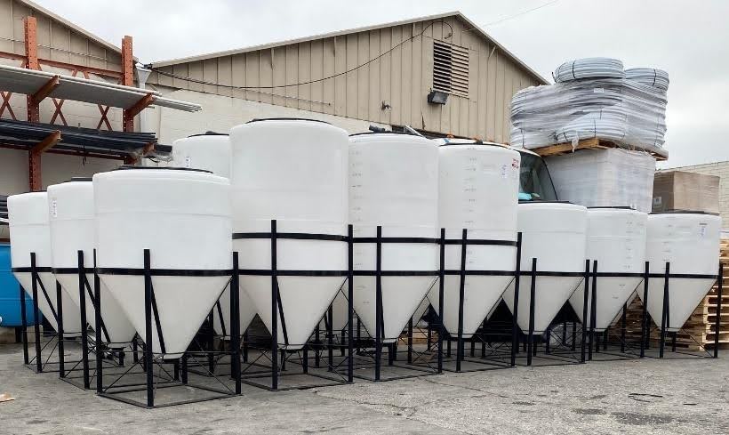
Cone bottom
-
Complete drainage, easier to clean out, easier to plumb, pumps can be tucked under the tanks, narrow and tall, more expensive
-
Doorway tanks
-
Great for awkward spaces that cannot accommodate vertical bulk storage tanks, more expensive, hardest to clean.
-
White, black, green
-
Most farms purchase white, natural, or translucent tanks. Some opt for green or black tanks that will not allow light penetration and therefore reduce instances of biological growth such as algae.
-
Wide and short or narrow and tall
-
Wide tanks are easier to get into for cleaning and adding fertilizers and do a better job of mixing fertilizers. Narrow tanks have a smaller footprint and therefore take up less space and better fit into tight areas without a lot of room to maneuver.
-
1.5 or 1.9 specific gravity
-
Unless chemicals, acids, and bases are being put into tanks in concentrate, 1.5 specific gravity water tanks are significantly more common than 1.9 specific gravity chemical tanks. They cost a lot less too.
When sizing a tank, it is important to consider how often you will need to fill it. Stock or concentrate tanks should be sized so that they do not require constant filling, yet won't sit too long. Batch or recipe tanks should be sized to ensure multiple fillings in a single day or set of days won’t be required. If a room consumes 100 gallons per day, we generally suggest oversizing the tank by 50 to 100% depending on how much space for tanks can be allocated. Be sure to calculate peak consumption and whether zones may grow in the future.
QUESTION #8 – WHAT IS THE DIFFERENCE BETWEEN INLINE FERTIGATION, BATCH TANKS, AND ROOM TANKS?
Inline fertigation means the nutrients and fertilizers are blended inline and delivered directly to the plants. There are no holding tanks, room tanks, blending tanks, recipe tanks, or batch tanks. Examples of inline systems would be:
-
A water tank that fertilizers are mixed in and feeds directly to the plants
-
Dosatron/Mixrite water driven dosing pumps that feed directly to the plants
-
Injection dosing systems such as HE Anderson, Netaflex, Argus, and Priva that feed directly to the plants
The advantage of an inline fertigation system is that they don’t require as much capital investment. There is significantly less hardware required including less filters, pumps, tanks, pressure gauges, fittings, valves, pipe, etc. Everything is simple, everything is easy.
The disadvantage of inline fertigation systems is that in many cases they do not offer the robust functionality of more elaborate systems. The ability to monitor flow rates, mixing, irrigation events, EC, pH, and other variables can be challenging. For many systems to operate correctly and accurately adjust EC/pH higher flow rates are required. Therefore, inline systems are more commonly found at larger farms with larger zones.
There is no minimum flow rate required when a mixing tank is directly connected to a zone. The minimum flow rate for Dosatron/Mixrite is relatively low depending on which dosing pumps are being used but can be just a few GPM. Automated dosing systems such as HE Anderson, Netaflex, Argus, and Priva operate best at 20 GPM and above when being used inline.
Batch tanks or recipe tanks involve setting up a water room around how many fertilizer recipes one intends to use. For example:
-
Recipe 1 – Veg tank
-
Recipe 2 – Early flower tank
-
Recipe 3 – Late flower tank
-
Recipe 4 – Flush tank
-
Recipe 5 – R&D tank
-
Recipe 6 – Chemical tank for cleaning lines
All 6 tanks would be plumbed into an irrigation manifold that branches out to the rooms. There would be a solenoid on the tank side of the manifold and on the zone/room side of the manifold. Therefore, if you want to send Recipe 2 to zone 15 one would open those two solenoid valves in unison and tank 2 would flow to zone 15 or any other zone that was opened in unison with tank 2.
This option is good for facilities that have fewer recipes than zones/rooms and would like the ability to send any recipe to any zone. If our example above was a facility with 20 zones/rooms, they would have the ability to send any of the 6 recipe tanks to any of those 20 zones. They will only require 6 tanks and pumps. If the same farm were to instead opt for room tanks or zone tanks, they would require 20 tanks and 20 pumps.
A drawback of this installation is that tanks must be larger since they feed many more zones than if each zone had its own tank. Operators are also limited in the quantity of recipes they can have.
Room tanks are setups that have a separate tank and pump for each room or zone. For example, a facility with 10 rooms would have 10 tanks and pumps. If those rooms each have 5 rows of benching, one could either put a single solenoid valve on the room to irrigate all 5 rows at once or a solenoid valve on each bench if they want the ability to water each row one at a time. Since each room only gets one recipe there is not much reason to separate the benches and irrigate them separately unless it is a multi-tier grow room and irrigating the top and bottom together is problematic.
Facilities that opt for a pump and tank per room spend a lot more money on their installation. They operate many more pumps than necessary, which means higher electrical costs and more maintenance. They also lose the ability to send a recipe to several zones.
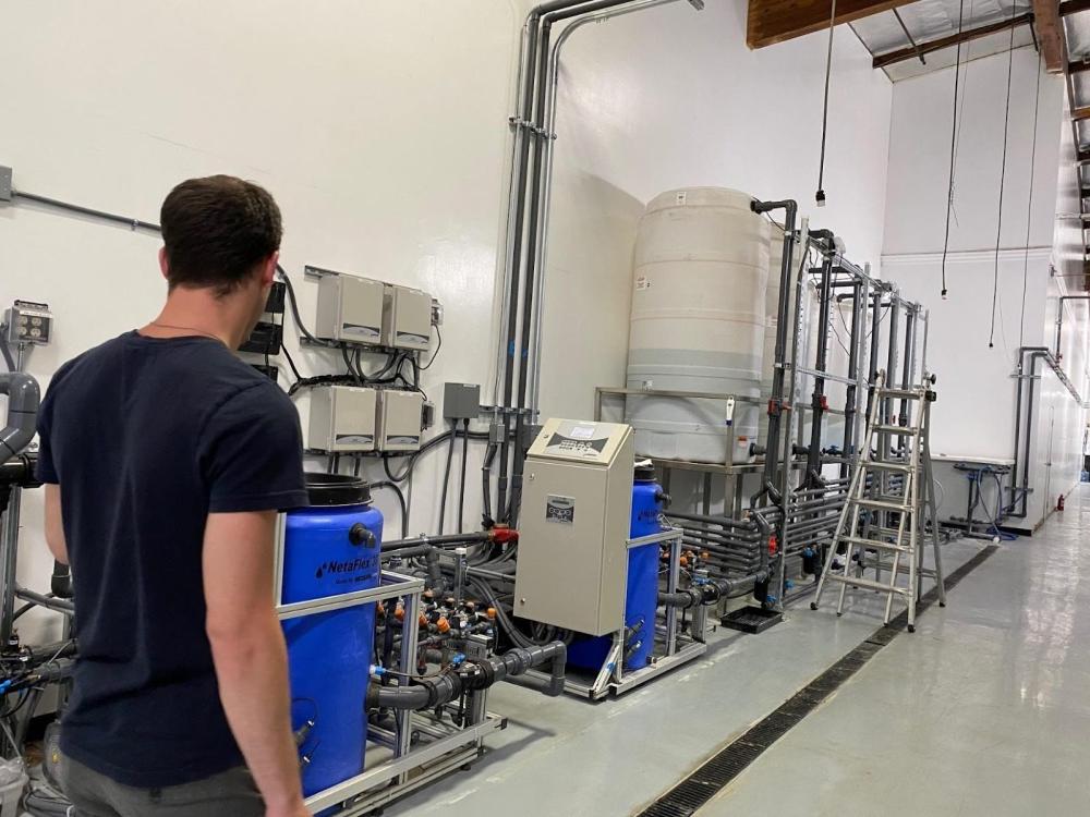
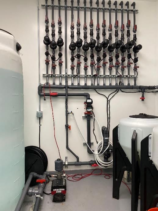
For this example, we are going to go with the 6 recipe tanks listed above. They are going to be in our water room for centralized control as opposed to being distributed throughout the facility.
QUESTION #9 – HOW DO I KNOW WHAT FITTINGS, VALVES, AND ACCESSORIES ARE NEEDED FOR A FERTIGATION INSTALLATION?
RO WATER SYSTEM
We now know that our water room will house the reverse osmosis water purification system. We have opted to install a 10,000 gallon per day (GPD) system which is larger than our need, but will allow us to fill tanks faster than the water will be consumed and therefore not need to stockpile as much clean water.
Some facilities donate much of their water room to water storage, a decision that does not have a good return on investment. By installing a larger than necessary RO system we can reduce the available water onsite to a mere 1000 gallons. What if the RO system breaks, you may ask? No problem, we have a dechlorinator and pretreatment carbon tank that will ensure the water is free from plant damaging chemicals. The small amount of EC/PPM that is in the water is a good thing, and we can slightly reduce our fertilizer feed to compensat
e. Having an RO is generally not necessary, but since most do and since we are illustrating how to design a optimal irrigation system, it is being included.
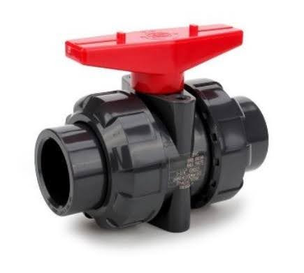
Valves placed around all equipment should be PVC true union ball valves like the Aquagation PVC true union ball valve, so that should the equipment require replacement or removal for service, lines can be closed and the equipment dealt with.
While PVC compact ball valves are glued in and require cutting the pipe to remove, True Union Ball Valves have Unions that open and allow access to lines and hardware.
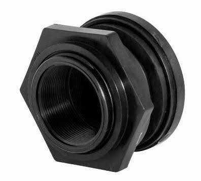
CLEAN WATER STORAGE RESERVOIRS
Clean water will enter the 1150-gallon Vertical Bulk Water Storage Reservoir from the RO system. This tank is only 48-Inches in diameter and 13-Feet tall. Therefore, it is tucked away, off to the side, and fits comfortably in any water room with a high ceiling. Proper greenhouse plumbing for this water tank requires a EPDM O-ring bulkhead fitting. For the inlet, where the clean RO water will enter the tank, it is sufficient to have a 1-1/2-Inch or 2-Inch bulkhead fitting. For the outlet, the fitting size depends on the distribution pump size. For a 55 GPM pump we would suggest a 2-Inch or 2-1/2-Inch pipe and depending on what else will be drawing off the RO storage tanks at the same time, possibly 3-Inch pipe. Calculating total water demand is easy to figure out (contact us for help).
RO Systems need a float valve to tell them when the holding tank is full so they can shut off, or turn on when it is depleted, and filling is required. A single pull, double throw float valve will accomplish this in one product or a float valve with a high/low shut off can be used. When selecting float valves, the most important factor is that the float valve is compatible with your RO system. Many RO controllers come with only a few communication ports, so be sure to check with the manufacturer or distributor before deciding on the float valve.
When installing multiple clean water storage tanks, you need to connect them with an outlet manifold and install True Union Ball valves - this will ensure the water level between the tanks remains even and tanks be isolated for service, repair, or cleaning.
CLEAN WATER DISTRIBUTION PUMP
When selecting a clean water distribution pump that will draw from your RO water storage tanks and send it throughout your facility, it’s important to consider a few things. Since RO water is corrosive, choose a pump with stainless steel internals and chemical resistant O-rings. If this step is overlooked, you will be replacing your pumps on an accelerated timeline. To size this pump, we only need to know the total RO water demand for the facility. Include fertigation, cleaning, spraying rooms, garden hose connections, and any other demands in gallons per minute. For example, a 3/4-Inch garden hose is around 23 gallons per minute and a 1/2-Inch garden hose is around 9 GPM, depending on water pressure.
If you have the extra budget, install two RO water distribution pumps per facility to ensure backup operation should one pump go down. The pumps are installed inline with bypasses for each. Every month the operator toggles between pumps to ensure they both operate regularly and have equal wear and tear. January pump 1, February pump 2, March pump 1, April pump 2, and so on throughout the year. When one of the pumps eventually breaks or needs service, simply close the valves around the pump so it can be taken out, and continue operating the system using the alternate pump.
Pumps often have built-in pressure gauges, but if not, it is highly recommended to install one on the outlet side of any pump. This gauge will indicate what is happening with the system while the pump is running, as well as when the pump is shut off. We once had a facility where the pump would shut off and then kick on/off, on/off, on/off over and over. It took a little testing to figure out that pressure was dropping while the pump was off since water was flowing back through the pump and into the RO water storage tank. Installing a check valve fixed the issue, but without the pressure gauge it would have been difficult to understand.
It is not often discussed but highly recommended that filtration be installed on the suction side of all booster pumps. These pumps are highly sensitive to solid particles being pumped through them, and a pump costing $2000 to $4000 can quickly become an expensive repair job if PVC shavings, Teflon tape, insoluble fertilizer, or other solids are accidentally pumped through the system. We often see this happen during start up testing when the installer did not properly flush and clean the system prior to operation. Installing a simple stainless steel mesh filter ensures this reality does not come to fruition.
Another best practice for pumps with female pipe thread (FPT) connections is to install with stainless steel pipe nipples. These pumps are water-cooled and can get hot when operating for extended periods of time, or when dry running. This heat needs to be dissipated as it gets hot enough to melt PVC pipe and fittings. Using a 6-Inch PVC pipe nipple allows for the heat being generated by the pump to dissipate prior to reaching the PVC fittings. After the stainless-steel pipe nipple, we suggest connecting to another PVC True Union Ball Valve to allow for isolation and repair should the pump require service.
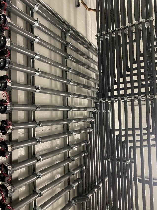
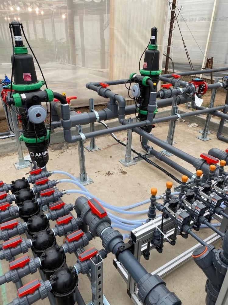
FERTIGATION SYSTEM PLUMBING AND INSTALLATION
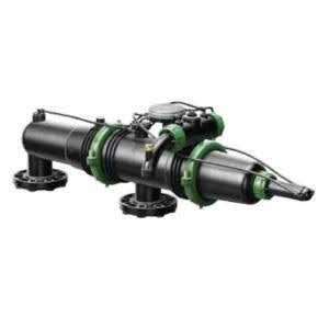
Depending on which fertigation system you intend on using (we have truly installed them all) - there can be nuances to the installation as each system has its own requirements. For this facility we have selected a venturi-based injection dosing system, and there are many options including the Netaflex 3G, FertiKit, Priva, and Rivulis C9400. The clean water distribution pump gets plumbed into the inlet of the system. Again, it is best to put PVC True Union Ball Valves around equipment and a bypass line for easy access should the dosing system go down.
Also, it is best to size pipes for flow rates, and not have a lot of bushings reducing or expanding line size. If your outlet is 1-1/2-inches, it is ideal to run that size pipe and install that size filters, flow meters, pressure sustaining valves, etc. If this cannot be done, it is generally okay, but system engineering should be checked by a professional - feel free to reach out as we are happy to assist when possible.
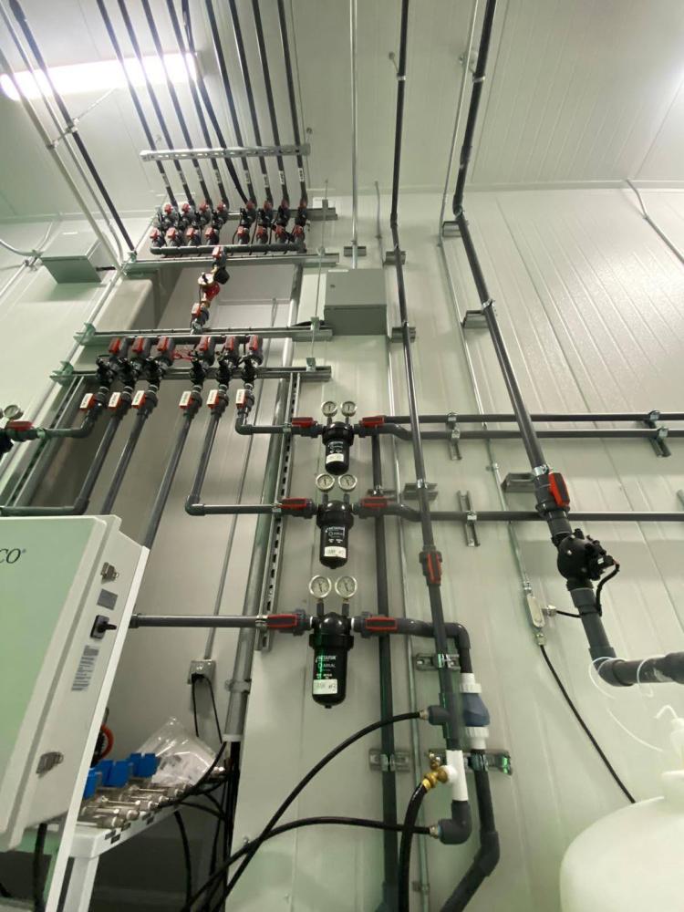
The industry best-practice is to install an air release valve ahead of flow meters, as air bubbles can cause them to not read correctly. Additionally, air that gets into an irrigation system can lead to issues such as air locks, vacuum, and other annoying problems that are often challenging to fix post-install. Check out some of our common air intake & release combination valves.
On the outlet side of the dosing system, there needs to be a flow meter first as this tells the system what is happening in real time and allows it to calculate the volume of water sent out. Generally, we like to install a 1 pulse per 0.1 gallons of water flow meter, but it depends on the system.
Although the dosing systems have their own EC and pH monitors, we often enjoy having another set for redundancy. Should you want another verification that the solution exiting the system is correct and ready to feed to your crop, this is where you would install those monitors.
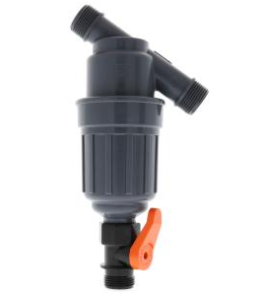
The next piece of hardware is going to be a master filter. High performance systems will install a self-cleaning filter to eliminate extra labor costs and potential neglect from employees. Since this filter is the first line of defense, it is often oversized to provide extra capacity and it is ideal that it self-cleans to ensure maximum operating efficiency. Too frequently we hear about a problem and come onsite only to find a completely compacted and clogged filtration system that has not been serviced or cared for. If there are too many other expenses and spending $2000 to $3000 on this style filter is not ideal, a simple manual irrigation disc/mesh filter for a few hundred dollars will suffice.
Before the outlet line from the fertigation skid connects to the distribution manifold, it is suggested to install a pressure reducing/pressure sustaining valve. The purpose of this valve is for healthy system engineering as it creates back pressure on the pump so it does not push out all the water in the system faster than it can be supplied and so that all downstream pressure will be consistent. This valve is a few hundred dollars, and again, if on a budget, the cost can be avoided by simply installing another PVC True Union Ball Valve that can be partially closed to regulate flow rate and pressure.
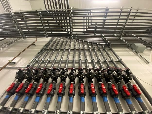
The dosing system outlet is now ready to connect to a distribution manifold that will fill recipe tanks. This manifold is generally installed in a vertical orientation so that water enters from the bottom and moves vertically up through the manifold.
Be sure to put PVC True Union Ball Valves, solenoid valves, and PVC Unions (not necessarily in that order) to ensure solenoid valves can be isolated and replaced as needed. PVC Spring Check Valves or PVC Ball Check Valves can be installed to prevent backflow.
In our example above, we have 6 recipe tanks, so this would mean 7 lines ( it is important to have a waste line). Just like with the clean water tanks, it is smart to plumb everything in with PVC True Union Ball Valves, Heavy-Duty Poly Bulkhead Fittings, and schedule 80 pipe and fittings. For the recipe tanks we have selected one reservoir that is a 1000-gallon cone bottom tank and five reservoirs that are 500-gallon cone bottom tanks. The 1000-gallon tank will be for the vegetative mix.
Each of the recipe tanks is connected to its own booster pump which should be installed in the same fashion as the clean water distribution pump, with a filter on the suction side, pipe nipples, air release valves, and in the case of recipe tanks, a filter on the outlet side as well or in the rooms ahead of the drip irrigation.
For a better user interface with the system and additional functionality, run the 6 outlet lines leaving the recipe tanks back into a single line with a flow meter and then branch back out to the 6 lines. This will provide crucial information back to the dosing system as to whether the system turned on and water flowed to the desired zone.
The first water meter, installed after the dosing system, will only tell you what happens when filling recipe tanks. This secondary flow meter will tell you what happens post-recipe-tank, on its way to the zone being irrigated. Farms often tell us they need costly sensors, many flow meters, or other monitoring devices to tell them if a row or zone of plants was fed. By taking the 6 outlet lines from the recipe tanks and running them back through a single flow meter and then branching out to the zones, you will always know if a pump operated correctly, if a solenoid opened as intended, and if there were unscheduled or unintended irrigation events.
INSTALLATION SUMMARY OF HARDWARE
-
Reverse osmosis water filtration system
-
Water holding tanks for clean water
-
Distribution pump for clean water
-
Fertigation system
-
Air release valve
-
Flow meter
-
EC/pH Sensor (Redundancy)
-
Master filtration
-
Pressure reducing/pressure sustaining valve
-
Distribution manifold to recipe tanks
The dosing system outlet splits into 7 lines - 6 recipe tanks and 1 waste line. There is a flow meter on this line prior to splitting.
Each recipe tank has an outlet and those 6 lines run through a single flow meter and then branch out to the zones. Therefore, there would be 6 lines into 1 line for the flow meter and then out to 14 zones. The 6 lines as well as the 14 zone lines each have a solenoid valve. If solution from tank 2 is being sent to ZONE 12, the controller would open those two respective solenoid valves. For diagrams and a deeper understanding of how to install this system, please contact MORR Digital Farming.
There will be more articles to come on the topic of drip irrigation equipment, fertilizer injection dosing systems, reverse osmosis water systems, and other similar topics. We have posts on how PVC fittings, valves, and pipe should be installed together, how drip irrigation manifolds should be constructed on benches in single and multi-tier greenhouse and indoor cultivations and compare and contrast data on how similar yet radically different fertilizer dosing systems affect cultivation success. Looking for information on a topic you don’t see covered? Shoot us an email.

About
MORR Inc.
MORR Inc. is a wholesale commercial agriculture distributor for planting, growing, and farming located in Los Angeles, CA. MORR Inc. supplies top of the line wholesale commercial hydroponic systems, commercial grow systems, a wide selection of grow lights and automated control systems, nutrient rich soils and growing media, a large selection of specialized advanced plant nutrients for different plant life cycles, dosing and drip irrigation systems, high tech environmental meters and automated systems, fans, filters, plant pesticides, plant fungicides, automated crop management systems, general commercial grow facility supplies and services, plus much more!
Call- 1-310-967-2022